Sabado, Agosto 1, 2015
Sabado, Hulyo 25, 2015
Week 6: Methods of Analysis(Mesh Method)
MESH CURRENT METHOD
The mesh current method
-uses the mesh currents as the circuit variables.
STEPS:
1. Identify all of the individual meshes in the circuit.
2. Assign a mesh current to each mesh.
3. Identify meshes in which the current is known because there is a
current source in an outside branch of the mesh.
4. Assign voltages to all of the elements in the meshes with unknown
currents.
5. Use KVL around each mesh to write loop equation.
6. Use Ohm’s law to write the resistor voltages in terms of the mesh
currents.
7. Insert the voltage expressions into the KVL equations to arrive at a
set of mesh current equations. If there are n unknown currents,
there should be n equations relating them.
8. Solve the system of equations to find the mesh currents
Learnings:
Sabado, Hulyo 18, 2015
Week 5: Methods of Analysis(Nodal Analysis Based on KCL and KVL)
Nodal Analysis Based on KCL
The steps in the nodal analysis method are:
- Count the number of principal nodes or junctions in the circuit. Call this number n.
- Number the nodes N1, N2, . . . , Nn and draw them on the circuit diagram. Call the voltages at these nodes V1, V2, . . . , Vn, respectively.
- Choose one of the nodes to be the reference node or ground and assign it a voltage of zero.
- For each node except the reference node write down Kirchoff's Current Law in the form "the algebraic sum of the currents flowing out of a node equals zero". (By algebraic sum we mean that a current flowing into a node is to be considered a negative current flowing out of the node.)
Example:
Use nodal analysis to find the voltage at each node of this circuit.
Solution:
Learnings:Solution:
- Note that the "pair of nodes" at the bottom is actually 1 extended node. Thus the number of nodes is 3.

- We will number the nodes as shown to the right.
- We will choose node 2 as the reference node and assign it a voltage of zero.
- Write down Kirchoff's Current Law for each node. Call V1 the voltage at node 1, V3 the voltage at node 3, and remember that V2 = 0. The result is the following system of equations:
The first equation results from KCL applied at node 1 and the second equation results from KCL applied at node 3. Collecting terms this becomes:
This form for the system of equations could have been gotten immediately by using the inspection method.
- Solving the system of equations using Gaussian elimination or some other method gives the following voltages:
V1=68.2 volts and V3=27.3 volts
We learn first where the nodes are in the circuit and finds a super node to solve the nodal analysis based on KCL and KVL law.After that, we can cumpute what are the blank in the circuit.
Sabado, Hulyo 11, 2015
Week 4: Wye-Delta
Wye-Delta
Three terminal networks are used in three phase connection, matching networks and electrical filters.
The Figure shows Wye (Y) and Tee (T) networks

The Figure shows delta (∆) and pie (Π) network.
Example:

Delta to wye conversion
It is easy to work with wye network. If we get delta network, we convert it to wye to work easily. To obtain the equivalent resistance in the wye network from delta network we compare the two networks and we confirm that they are same. Now we will convert the 2nd figure (a) delta network to the first figure (a) wye network.
From the 2nd figure (a) for terminals 1 and 2 we get,
R12 (∆) = Rb || (Ra + Rb)
From figure 2 (a) for terminals 1 and 2 we get,
R12(Y) = R1 + R3
Setting wye and delta equal,
R12(Y) = R12 (∆) we get,


Wye to Delta conversion
Example:

Now we will solve a problem how to convert delta to wye network. It will give clear concept.
converting the delta network to wye network.


The equivalent Y network configuration is shown below.

For conversion to wye network to delta network adding equations (v), (vi) and (vii) we get,
R1R2 + R2R3 + R3R1 = RaRbRc(Ra +Rb + Rc)/(Ra + Rb + Rc)2
= RaRbRc/(Ra + Rb + Rc) —————— (ix)
Dividing equation (ix) by each of the equations (v), (vi) and (vii) we get,
Ra = R1R2 + R2R3 + R3R1/ R1
Rb = R1R2 + R2R3 + R3R1/ R2
Rc = R1R2 + R2R3 + R3R1/ R3
Learnings:
Learning to Identify what network it is to know what formula are we using; the wye-delta or delta-wye.
Sabado, Hulyo 4, 2015
Week 3: Basic Laws (Current and Voltage Division)
Voltage Division
The voltage division rule (voltage divider) is a simple rule which can be used in solving circuits to simplify the solution. Applying the voltage division rule can also solve simple circuits thoroughly
Voltage Division Rule: The voltage is divided between two series resistors in direct
proportion to their resistance.
Example:

Solution:
the Ohm's law implies that
Applying KVL
Hence
i(t)=v(t)R1+R2 .
Substituting in I and II
v1(t)=R1v(t)R1+R2 ,
v2(t)=R2v(t)R1+R2 .
Consequently
v1(t)=R1R1+R2v(t) ,v
2(t)=R2R1+R 2v(t) .
CURRENT DIVISION
Current Division
A Current Divsion circuit is a circuit in which the main current from the power source is divided up in the circuit and, thus, different amounts of current are allocated to different parts of the circuit.
Example:
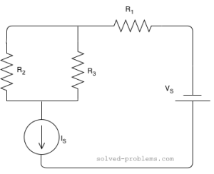
Suppose that R1=2Ω , R2=4Ω , R3=1Ω , IS=5A and VS=4V
Solution:
IR2=R3R2+R3×IS=11+4×5=1A
IR3=R2R2+R3×IS=41+4×5=4A .
IR1=IS=5A .
KCV around the loop assuming the positive terminal of the current source to be the one at bottom:
+VIS−R3×IR3−R1×IR1−VS=0
VIS=R3×IR3+R1×IR1+VS
VIS=1×4+2×5+4=18V
Solution:
IR2=R3R2+R3×IS=11+4×5=1A
IR3=R2R2+R3×IS=41+4×5=4A .
IR1=IS=5A .
KCV around the loop assuming the positive terminal of the current source to be the one at bottom:
+VIS−R3×IR3−R1×IR1−VS=0
VIS=R3×IR3+R1×IR1+VS
VIS=1×4+2×5+4=18V
Mag-subscribe sa:
Mga Komento (Atom)